This guidance document contains background information on design principles and strategies, and includes checklists for design teams to follow to help with the design process. The guidance covers passive solar design principles and their application to government buildings.
How well passive solar design strategies might improve the performance of a building depends entirely on the natural resources and restrictions of the building’s environment. As the phrase implies, ‘passive buildings’ must have a closer relationship with their surroundings (much more so than a conventional building) to achieve a comfortable internal environment with a minimum of resource use.
Before the design of the building can go ahead, a site investigation should be carried out. If a particular site receives little or no sun, there is little or no capacity for passive solar heating and the design must find other solutions for conditioning the building. Similarly, a site’s wind resource will affect the natural ventilation strategy. A building’s form, orientation and set out all need to be designed to make the most of the available resources.
3.1.1: Design considerations
As the local site and climate can determine the success or failure of a passive solar building, there are several fundamental considerations. These are as follows.
Overshadowing
The degree of solar access must always be determined before the design team can select appropriate passive design strategies. Topography or surrounding buildings may overshadow a site. Longitude will also determine the solar angles over the course of the year. The solar access of the site can be investigated using either a computer model of the site and neighbourhood or by using a sunpath diagram (available online from the Centre for Building Performance Research (CBPR)).
Figure 2: An example manual shading study using the solar diagram from the CBPR
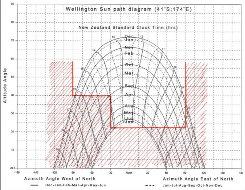
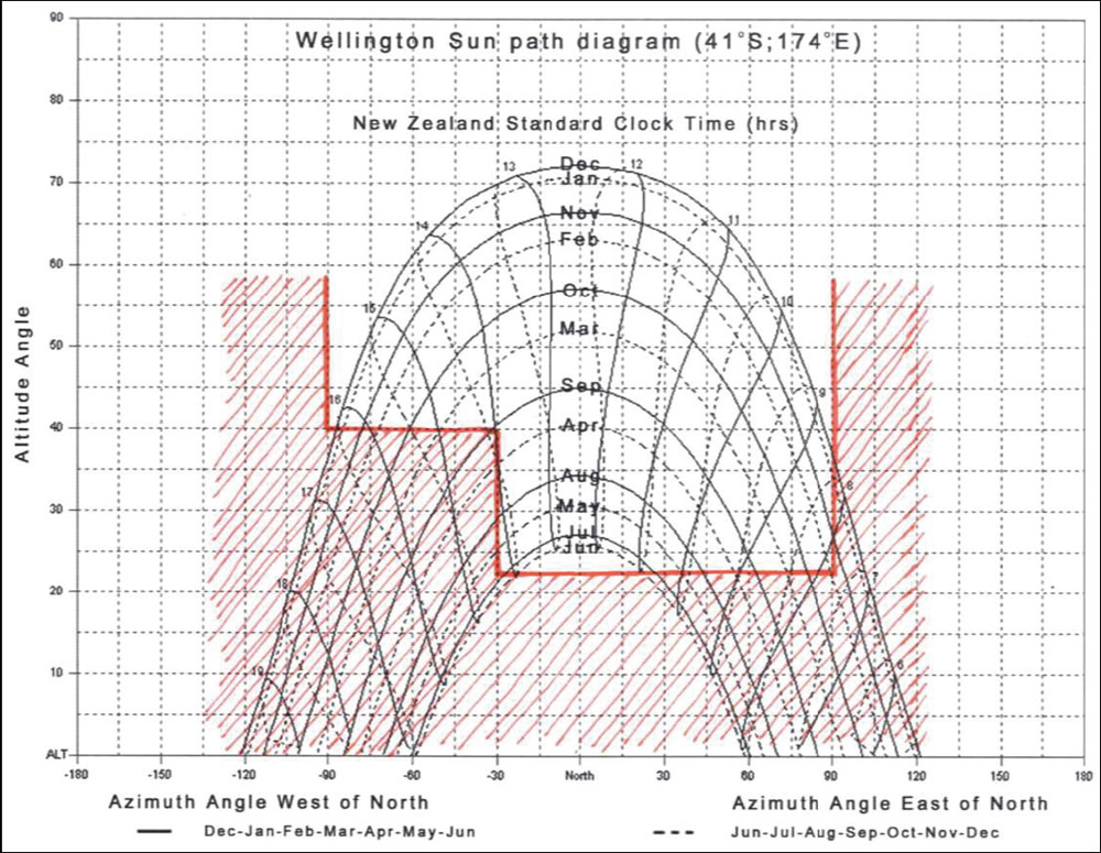
Once an overshadowing analysis is complete, the information is used to orientate the building on the site. The optimal angle for building in the southern hemisphere is a direct northern exposure. However, this may not necessarily be possible or desirable. As a rule of thumb, a building facing 30 degrees either side of due north will receive about 90 per cent of the optimal winter solar heat gain (Department of Energy, 2000). During winter months, the building must maximise any solar gains to help heat the building, while in summer months sun angles are higher so solar gains may need to be controlled, and in some instances mitigated to prevent overheating.
Windflow
The natural ventilation strategy will depend on the amount of windflow at the site. Some sheltered sites may have to depend on temperature-driven ventilation as wind speeds may be too low. Other exposed sites may have wind speeds too high for simple windows that can be opened and may require an engineered solution. It is important to remember that wind and temperature vary widely within a city and some sites can have their own unique microclimate. It may be necessary to collect weather data from a particular site for a time to gain a complete understanding of the site’s unique conditions.
A wind rose is a visual representation of the wind conditions at a site generated from historical data. It plots average speeds and prevailing direction. It is relatively easy to produce from historical data, or from some building simulation software. Information from the wind rose is then used to find the best orientation for the building to maximise wind-driven ventilation.
Figure 3: Wind rose for Wellington

Image: Source - Taken from Autodesk Ecotect
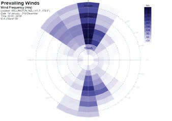
Image: Source - Taken from Autodesk Ecotect
Temperature and humidity
It is important to design any building to suit the conditions it will experience throughout its life. In passive buildings, the building fabric and the external conditions combine to maintain a comfortable internal environment without reliance on mechanical systems. Temperature and humidity are two of the main determinants of human comfort. The external conditions need to be examined to estimate the level of performance required from the building fabric. It is often useful to plot climate data on a psychometric chart (which shows the properties of air and the water contained in it at different temperatures). This gives the design team a visual reference as to the difference between external and desired internal conditions. Remember, too, that design temperatures for a location are based on hot and cold extremes rather than historical averages.
Planning restrictions
A site’s limitations are not always physical. Local planning laws such as zoning rules, solar access planes and height restrictions, and national laws such as the New Zealand Building Code and the Resource Management Act, all apply restrictions to how a site can be built on. Preservation laws may also be an issue if retrofitting existing buildings.
Any existing infrastructure such as power lines, water and gas mains, sewers and drainage lines will have to be worked around. Traffic access requirements (both road and foot) may also influence the building’s design, particularly parking requirements, which may have an effect on solar access, and building layout.
New Zealand currently has a performance-based building code, meaning that territorial authorities should still accept solutions which do not necessarily fit neatly into the code structure, but which can prove they meet the intent of the code. Passive solar design features often fall into this category. It may be necessary for a passive solar building to prove compliance with the New Zealand Building Code.
To avoid having Building Code compliance become an obstacle to the design aims of the building, the territorial authority should be consulted early in the design process. This will keep them informed about the design intent, and will allow them to accommodate design features that do not neatly fit the Building Code’s acceptable solutions.
Layout and form
Consider the location of all habitable spaces, which are likely to have the greatest heating and lighting requirement. In most cases, these should be located towards the northern facade of the building to receive the most benefit from the sun. Spaces that are used least or are to be left unconditioned (eg, storage areas, toilets, lifts or garages) should be placed along the south wall where they can act as a buffer between high-use space and the colder south side of the building (Arizona Solar Centre). Areas of a building that are alike should also be grouped together so areas of similar gains and conditioning requirements can share common passive design strategies.
Building users
The most important factor in the ongoing environmental impact of a building is how the occupants use it. The building must meet the needs of the users or it will not be fit for purpose. Government buildings have the advantage that the client is already known and their needs (hours of operation, organisational structure, attitude to environmental issues) are reasonably well understood. These define the building’s energy use and demands, and therefore the passive design approach. The organisational structure should also play a role in determining the building layout.
To ensure the building is used properly once built, the users need to have a good understanding of how the building works and how their actions affect the building’s performance. The design team should involve future users and facilities management staff in the design process, and develop a building user’s guide to inform occupants of the building’s design intent. This means they are better able to maximise the performance of their building, and the utility they receive from it.
The commissioning of buildings is extremely important in making sure the building performs as intended and achieves the design performance targets. Again, the facilities management team should be involved in a full commissioning process, and ongoing tuning should continue for the first 12 months of operation. The Ministry for the Environment has published guidance on best practice commissioning of buildings which is available from the Ministry’s website. Details have also been included in the Further Reading section of this guidance document.
3.1.2: Site, climate and building design checklist
- Carry out a study of solar access, overshadowing and wind flow at the site.
- Examine temperatures and determine the difference between external conditions and those desired inside the building.
- Liaise with your territorial authority to determine restrictions on the site. Inform them of your design intent and find solutions to any regulatory issues. Maintain this link throughout the design process.
- Finalise the building orientation and layout according to site conditions and organisational structure.
- Develop a user guide and carry out commissioning to best practice guidelines.
Daylight design is the use of light from the sun and sky to complement or replace artificial light (O’Connor et al, 1997).
Daylight consists of three components:
- direct light from the sun
- diffuse sky components or daylight scattered in the atmosphere
- daylight reflected from surrounding surfaces, such as buildings and the ground.
Daylight is generally preferred above artificial lighting. It is free, has perfect colour rendering and a positive effect on human well-being (International Energy Agency, 2001). Research has linked good daylighting with worker productivity and comfort, and with some daylit workspaces having lower tenant and employee turnover rates (O’Connor et al, 1997).
Passive daylighting systems use windows and shading or redirecting devices to enhance the quality and performance of daylight in a space. Decisions made in the early design phase can determine the overall success of the system. Appropriate window products and lighting controls are used to optimise daylight performance and to reduce electric lighting needs, while meeting the occupant lighting quality and quantity requirements (O’Connor et al, 1997). Artificial lighting and its associated requirement for cooling energy, contributes an estimated 30 to 40 per cent of a commercial building’s total energy use (O’Connor et al, 1997). For this reason, daylighting is the most cost-effective strategy for targeting these energy uses, as savings of 40 to 80 per cent are achievable through effective daylighting design in perimeter zones of office buildings (Levine et al, 2007).
Two major sources of heat gains in commercial buildings are artificial lighting and sunlight. The heat gains from artificial lighting can be reduced when a predominantly daylighting system is used (International Energy Agency, 2001) and limiting direct sunlight transmitted into the space will prevent overheating (Levine et al, 2007). Therefore, daylighting strategies need be optimised to use as little artificial light as possible, but even the best daylit buildings will need some complementary or artificial lighting for after-hours use.
3.2.1: Design strategies
It is extremely important to consider daylighting strategies from an overall perspective. It is not just a question of illumination available on a horizontal surface, but the interactions between light quality, climate, building function, orientation, occupants, solar gains and building design (Hastings, 1994).
Building form
Selecting an appropriate building footprint can allow a building to maximise the use of the daylight available, where long narrow footprints are preferable to square ones (O’Connor et al, 1997). The following floor plans are some examples of layouts that distribute and use daylight effectively.
Figure 4: Building footprints for best daylight access
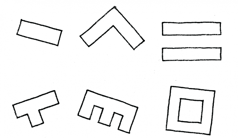

These building forms are not always appropriate and can produce ‘cookie cutter’ buildings. In these situations, systems that allow daylight into the core of the building, such as clerestories, atria and light-wells are other options.
The following features should also be included where possible (O’Connor et al, 1997):
- north/south exposures, as they are generally preferable to east/west (preferably within 30 degrees of the north/south axis). Remember that this rule of thumb refers to true north rather than magnetic north (around 20° east of north, though this varies throughout the country)
- windows on two sides of the space, to provide better daylight distribution
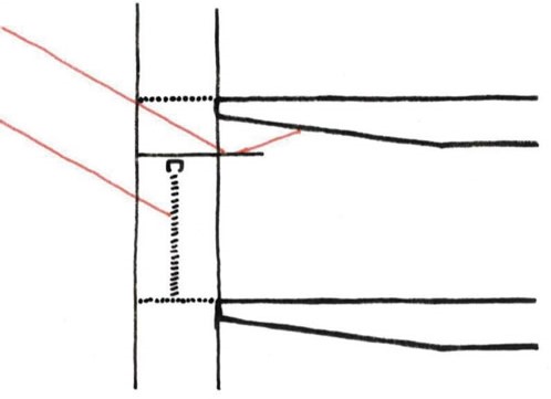
- room depths within one-and-a-half to two times window head height for adequate light levels and balanced distribution.
Figure 5: Daylighting guidelines for room dimensions

Room features
When designing the room layout, spaces should be located relative to their tasks. Tasks requiring higher light levels and that are performed regularly should be located near windows, and tasks with little need for daylight that are performed infrequently should be located in non-perimeter or core areas (O’Connor et al, 1997).
Furniture layout should not block light to spaces further from the window. It is important that full-height partitions, bookshelves and files are not positioned parallel to window walls (O’Connor et al, 1997). If partitions are in use, clear or translucent materials in the upper portion of full-height partitions are needed (O’Connor et al, 1997).
When selecting materials, use surfaces with high reflectance as these will result in higher light levels at the rear of the space and the distribution of light is more even. Dark surfaces should only be used for emphasis and kept away from windows (O’Connor et al, 1997). The recommended surface reflectance is:
- ceilings: > 80 per cent
- walls: 50–70 per cent
- floors: 20–45 per cent.
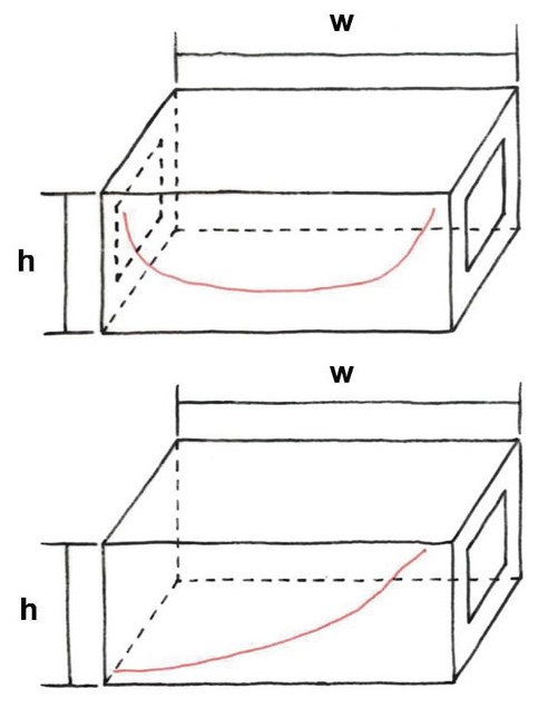
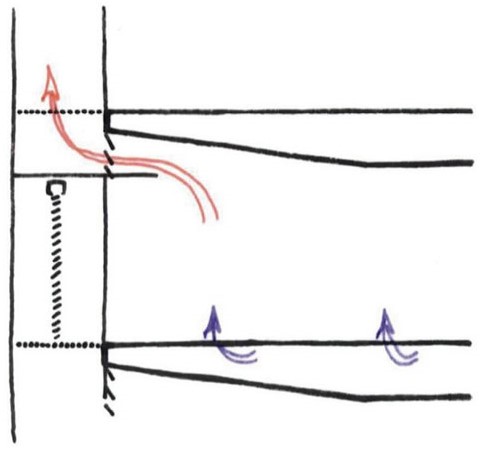
Introducing a sloped ceiling is a simple way of improving daylight distribution at the rear of a space. Locating ducting at the back of the space will also allow high windows to fit within the standard floor-to-ceiling height (Hastings, 1994).
Figure 6: The use of a sloped ceiling to improve daylight penetration into a room

Windows systems
Windows on every orientation can provide useful daylight, but each orientation needs to be treated differently. North facades provide good access to strong illumination, but vary throughout the day and require shading. South facades provide high-quality, consistent daylight with minimal heat gains, but thermal loss occurs on cooler days. East and west facades also require shading, but have to take account of lower sun angles (O’Connor et al, 1997).
The practical depth of a daylit zone is typically limited to one-and-a-half times the window head height. With standard window and ceiling heights, adequate daylight extends to within 4.6 m from the window (O’Connor et al, 1997). Note that the higher the window, the deeper the daylight reaches into the room.
A good approach for excellent daylighting and glare control is separating view and light windows. Use high-transmission, clearer glazing in high level (or clerestory) windows, and lower-transmission glazing in view windows to control glare (O’Connor et al, 1997).
Diffuse glazing on the interior face and glass blocks redirect skylight to the deeper parts of the room, to a limited degree, from where the sky is not visible. The same type of prisms can also be used to redirect sunlight to the ceiling, giving shading in the front of the room, and generally increase daylight levels by diffuse reflection from the ceiling (Hastings, 1994).
Insulated glazing units can be used to reduce the heating losses normally associated with single-glazed windows and can still allow a good distribution of daylight (Hastings, 1994).
The following principles should be used when designing the daylighting system (O’Connor et al, 1997):
- large windows require more measures to control glare and heat gains
- strip windows should be used as they provide a uniform distribution of daylight
- locating windows near room surfaces will provide good distribution as these surfaces will help reflect and redistribute the daylight
- glazing area should not be wasted where it cannot be seen, such as below desk height, as it wastes energy, causes discomfort (especially in winter), and provides little benefit.
Daylight controls
At night, electric lighting must be able to provide all necessary lighting. In addition, during the day, whenever daylighting provides insufficient light levels for a particular task, electric lighting can be used as an additional source of light. Daylight controls are an invaluable tool that switch electric lights off (or dim them down) when not required. The controls are programmed with a desired setpoint and then adjust the electric lighting to top up the available daylight. As electric lighting contributes to a building’s cooling load, using daylighting controls will also reduce the energy used for cooling the building, further reducing operating costs (International Energy Agency, 2001).
3.2.2: Daylighting checklist
- Use information from the site investigation to choose appropriate building orientation, form type, orientation and internal layout.
- Select window shape and position.
- Select appropriate shading devices and glazing types to control glare and solar gain.
- Consider the thermal implications of daylight design.
- Ensure the interior colour scheme is suitable for daylight design.
- Investigate integrated light control systems for energy efficiency.
In an attempt to incorporate daylighting into a building, designers often make the mistake of simply increasing the glazing area as much as possible. Unfortunately, good daylighting is not that simple. Large, unprotected areas of glazing can lead to discomfort to occupants through glare, and high solar gains can affect the building’s energy use. It is important when designing a building that these effects are considered in the overall design strategy.
Glare is usually at its worst when the sun is low in the sky; in the early morning, late afternoon, and during the winter months. While glare from the sun is usually only a short term phenomenon, the effects can be quite strong and can result in a marked reduction in staff productivity, for example, they may not be able to read a computer screen. As glare effects vary over time and location and even person to person, the ideal shading strategy should be relatively flexible and allow the building users to adjust the shade to suit the immediate situation. The best examples are adjustable louvre blinds that an individual can raise or lower and then tilt to block their glare source.
Solar gains are required to reduce heating loads during winter months, however, too much solar gain can result in uncomfortable internal temperatures or increased cooling energy if air-conditioning is installed. The shading design needs to find the balance between the two, normally through optimising the shading to eliminate summer sun, while allowing winter sun to pass into the building. To reduce heat gains, external shading devices are the best-performing option; internal shading slows heat down, reducing peak loads, but still allows the majority of the sun’s heat into the space. Note that this contradicts the ideal case for glare mentioned above.
Design teams need to apply the information from the site shading study to the building envelope when considering effects from direct sun. It is important to remember that the northern facade will often receive the most solar gains during winter, when the low-angle sun penetrates deeper into the space. The eastern and western facades will also receive high heat gains, particularly the west, which can often become superheated by late afternoon sun after a full day of solar gains. Furthermore, during a New Zealand summer, the sun rises and sets approximately 30 degrees to the south of due east and west, and if a building has extended hours of operation the southern facade may need shading in some way. Sunpath diagrams are available from the Centre for Building Performance Research [Victoria University of Wellington website].
3.3.1: Design strategies
Many of the shading design strategies were discussed in the related section on daylighting. A good shading solution should compliment the daylighting design, along with any other strategies being incorporated into the building.
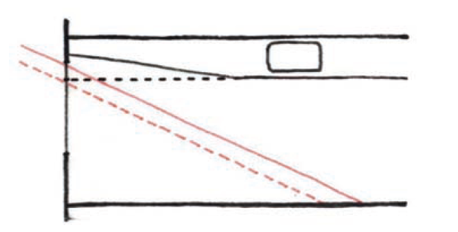
Fixed shading devices including overhangs, light-shelves and diffuse panels can be used to shade and redirect light into a space where it is useful. Using these shading systems will also reduce solar gains and glare. Several possible design options are discussed below.
Overhangs and sidefins
Permanent devices such as overhangs are common in hot climates and present the advantage of having little or no effect on views and, when placed above the top of a window, they allow low-angle winter sun and block high-angle summer radiation. The advantage of using permanent window protection is generally limited to windows facing north. For windows facing east or west, other devices must be used because of the lower sun angle. Vertical projections or sidefins offer a way to shade these windows (Hastings, 1994).
Figure 7: Overhangs (left) and sidefins (centre)

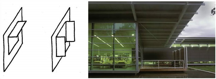
Fixed louvres
The design of the louvre arrangement needs to be optimised to eliminate undesirable sunlight. This affects the depth (often determined by the product used), spacing and orientation of the louvre blades. Horizontal louvres are best used on the northern facade, where the sun tends to be higher, while the western and eastern facades would benefit from vertical louvres, or a different strategy altogether, such as blinds or external mesh screens, as the sun is lower in the sky in the mornings and afternoons and sunlight will pass directly through horizontal louvres. Louvres can also be automated for maximum efficiency; however, as they are on the exterior, they can be difficult to maintain and obscure external views (Hastings, 1994). The considerations of maintenance and effects on external views should therefore be added to the decision-making process.
Figure 8: Horizontal and vertical louvres

Light shelves
Light shelves block direct sun while reflecting daylight off the room’s ceiling deep into the space. Light shelves are discussed further in the Daylighting section of this document.
Roller blinds and internal louvres
Fully adjustable shading options are the most effective at dealing with glare. They allow the occupants to adjust blinds or louvres to suit the glare source at the time. The disadvantages of movable devices are that they obscure the external view and release absorbed solar gains into the room. This can be diminished with reflective materials, but these materials can result in visual discomfort associated with glare. The upside is internal shading devices are often included as a fit-out item and can easily be retrofitted into a wide variety of existing buildings.
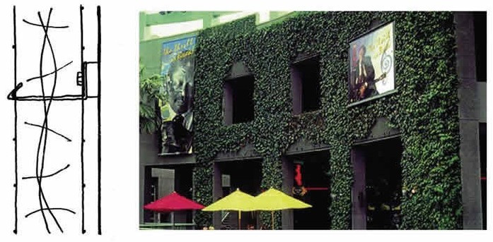
Screens
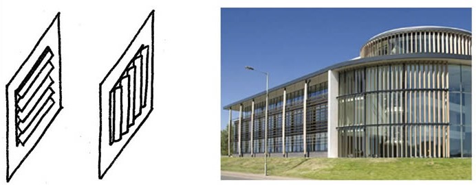
Mesh screens hung around the outside of the building are a very effective shading device and can be a striking aesthetic feature. They have the advantage of providing an even amount of shading over the entire building facade, rather than the ‘all or nothing’ effect of louvres. The evenness of the shading also means that occupants maintain reasonable connection with the external view, depending on the level of transparency of the mesh. Internationally ‘green screens’ have been used, which use a climbing plant between two metal grids, such as reinforcing mesh. Using plants on the side of a building gives an interesting aesthetic and helps reduce a building’s visual impact on the environment. The degree of shading depends on the density of the planting. Green screens do have a relatively high maintenance requirement and require irrigation.
Figure 9: A greenscreen (left) with the two meshes hung on the solid façade

Double skin facades
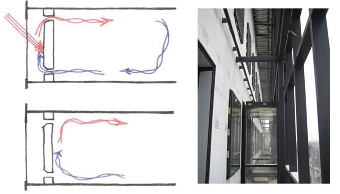
A double skin facade provides a sheltered space outside the occupied space where blinds or louvres can be set. This allows the occupants to benefit from the flexibility of movable shading while also preventing solar gains from re-radiating back into the occupied space. Blinds are automated and controlled by light sensors on the facade, which raise, lower and open or close the blinds to suit the conditions at any given time during the day. The building’s management system (BMS) integrates the control of the blinds with the conditioning systems to ensure efficient running of the building. Ideally, there should always be a manual override to allow user control if required. For best results, a double skin facade should be on the northern facade of the building so that it receives as much heat from the sun as possible to drive the natural ventilation. Double skin facades can be expensive, as they are essentially doubling the glazing requirements for that face of the building, although they have the benefit of having other passive design strategies, such as light shelves or natural ventilation, fully integrated.
Figure 10: Shading strategies within a double skin facade; automated blinds are hung between the two glazing skins

3.3.2: Shading checklist
- Assess potential areas of concern for glare and overheating.
- Select appropriate shading solutions for each facade depending on orientation and site conditions.
- Incorporate shading with the intended daylighting strategy.
- Refine to the final solution taking account of heat gains, glare and glazing type.
The combination of thermal mass, glazing type and design, and insulation form the three pillars of good passive design. Their interaction needs to be carefully considered to achieve the best result.
Thermal mass stores heat when there is an excess of passive solar energy and/or internal gains in a building, and releases the stored heat as the building starts to cool down. Mass also reduces the swings in peak temperature and, for this reason, thermal mass is often required in a passive solar building to bring the temperature variations within acceptable limits and/or to reduce the peak cooling loads.
Thermal insulation, on the other hand, slows the transfer of heat through walls, floors and ceilings, both inwards and outwards. This results in reduced energy costs and helps maintain a uniform temperature by retaining heat during the winter months and keep the building cool during the summer months.
Thermal insulation in buildings is an important factor in achieving thermal comfort for occupants and it helps reduce the energy demands of heating and cooling systems. The most important component of insulation is its R-value (or thermal resistance), where the greater the R-value the better it is at resisting heat movement.
Several types of insulation products exist including insulation batts and blankets, foam insulation, blown insulation, rigid insulation panels, and insulating materials incorporated into other products such as cladding and structural components. Ideally, insulation should be kept separate from the internal environment as some types of insulation collect dust and can add particulates to the air.
When conditioning a building through passive solar design, the design team needs to understand the likely internal gains within the space and their interaction with the desired internal conditions. A lot of passive design literature assumes a predominantly heated building and then makes recommendations on how to use thermal mass and insulation to reduce heating energy. Some building types will have a higher cooling requirement due to the high internal heat gains from people, office equipment and so on. In this case, thermal mass should be used to cool the building by storing heat from the occupied space during the day and releasing it when the room is unoccupied.
The relative positioning of the building’s thermal mass and insulation are one of the keys to passive solar design (Hastings, 1994). In a low-gain building, mass should be located to receive solar gains from the sun, normally on the floor or as a trombe wall (a thermally massive wall in full view of direct sun). In a building with high internal gains, the mass should be placed away from the sun to prevent the space becoming superheated by the combined effect of mass and the internal gains. This is usually achieved by absorbing excess heat in exposed ceilings.
The building’s facade design needs to be balanced with daylighting requirements. Visible light transmission needs to be balanced with solar gains, while also considering glare effects. Solar gains are the free heat from the sun central to passive design, although this can be undesirable in high heat-gain buildings. Glazing areas and glass selection need to be optimised for all facades, and may vary around the building depending on orientation.
3.4.1: Design strategies
There are many thermal mass systems commonly used, some of which are detailed below.
Mass storage systems
A mass storage system combines collection, storage and transport of solar energy in one unit and allows the building to work simultaneously as a solar collector and as a storage device. A trombe wall is particularly well suited for buildings that have significant heat load during the night, as the release of heat from mass during this time can help meet the night heating load, avoiding or minimising the need for auxiliary heating (Hastings, 1994).
Figure 11: A trombe wall

Transparent insulation systems
The performance of the mass wall system can be greatly improved with transparent insulation as the glazing. Solar radiation is partially transmitted through the insulation to be absorbed at the exterior surface of the wall. Depending on solar radiation, the wall heats up and temporarily transfers heat from the outside to the inside. During periods of weak or no radiation, heat losses are minimised by the insulation level of the material layer on the outside of the wall. In periods of higher radiation, the external walls absorb radiation, store heat and can temporarily heat the surface of the adjoining space (Hastings, 1994).
Figure 12: The internal structure of transparent insulation

Insulation
The role that insulation plays in the building is determined by its placement. When used in the building envelope, it is preventing heat flow from the inside to outside, either containing heat within the building or preventing it from entering. Insulation can be used to isolate thermal mass, shielding the massive elements from unwanted solar gains, or shielding occupied areas from the unwanted effects of thermal mass.
It is important to note that any building material has an insulating effect. This is most apparent with floor coverings on concrete slabs. Timber or carpet will effectively insulate the slab and reduce (or eliminate) its effectiveness as a heat sink. Internal strapping and lining to walls will have the same effect, as will acoustic ceiling tiles.
Night purge
In high heat-gain buildings, there may be residual heat at the end of the day which, if retained overnight, can lead to overheating the next day. To remove the residual heat, the building is ventilated overnight. The cool night air draws the heat out of the thermal mass or insulated envelope and releases it back outside. With a lower initial temperature at the start of the next day, the building is less likely to overheat, thereby improving comfort and reducing cooling requirements.
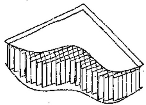
Thermal labyrinths and rockbins
Thermal mass can be used within the air delivery system to moderate the temperature of the supply air. These systems include complex designs like thermal labyrinths and rockbins, although they can also have simple solutions such as running air supply ‘ducts’ inside hollow concrete structures.
Figure 13: A thermal labyrinth (left) and a rockbin (right)

Unlike the thermal mass used in the building envelope that is designed to control heat variations over a day, a thermal labyrinth or rockbin attempts to moderate temperatures over an entire year. Surplus heat is removed from air coming into the building during summer and is retained until the winter, when it is used to warm the cooler incoming air. As a result, rockbins require very large amounts of mass to maintain a stable temperature over the full year. This, along with the space requirement, makes them particularly expensive unless ‘waste mass’ can be sourced such as old kerbstones or waste rock diverted from landfill. A cheaper alternative is to use the concrete structure of the building as the air-delivery system, ducting the air through hollow concrete beams, or within hollow-core or sine-wave slabs. Ground source heating is a similar option, where pipes are laid horizontally below the surface and used to draw air along them and into the building.
3.4.2: Thermal mass and insulation checklist
- Determine likely gains and therefore predominant load (ie, heating or cooling).
- Arrange mass and insulation to best suit the findings from above.
- Select glazing in coordination with the shading and daylighting strategies.
- Refine to the final solution, taking account of natural ventilation.
- Test using computer simulation throughout the design process.
Studies have linked increased fresh air rates with increased occupant health (Fanger, 2006). Current sustainable building practice is to supply work areas with above-code levels of fresh air. Typical levels are 150 or 200 per cent of the minimum Building Code requirement. Note the Code requirements will vary depending on the type of building. In a mechanical system, the increased fresh air rates carry an energy penalty, as a larger volume of air needs to be heated or cooled to suit the building. A natural ventilation strategy supplies fully fresh air with no conditioning system. This approach provides the benefits of high fresh air volumes with a reduced energy use for heating and cooling systems and mechanical ventilation.
It is important to distinguish between naturally ventilated buildings, in which fresh air is supplied through unforced means, and a building that simply has no cooling or heating capacity in the mechanical ventilation system. Similarly, buildings using an economiser cycle, where the HVAC system brings full fresh air into the building to reduce cooling energy, are not naturally ventilated buildings in the true sense, though an economiser cycle is an effective energy-saving feature.
Natural ventilation strategies make use of two generators of air movement: the stack (or buoyancy) effect where heated air rises, and wind which generates air movement through pressure differences across or within a building. How effectively the stack effect will ventilate a building depends on the gains within the building. Some rooms (eg, school computer suites) will have relatively high gains and air will be heated by equipment, occupants and solar gains. The heated air will then want to rise through the building. The natural ventilation design should take advantage of this fact, release the heated air from the building at high level and then draw fresh air into the building through the facade. For building types that have lower gains (for example, hangars and maintenance sheds) the stack effect may not be the most suitable and they would be better served by wind-driven ventilation. A detailed understanding of the opportunities for using wind-driven ventilation should come from the site analysis undertaken before the design phase starts. The building then needs to be designed to maximise the potential of that site.
Predicting exactly how air will move through a building is extremely difficult. Openings and airflows need to be sufficient to provide the required level of ventilation, cooling and fresh air. Larger buildings may lend themselves to some basic computational fluid dynamic (CFD) analysis as part of the building simulation process; however most projects will have to rely on engineering guidelines and experience.
A naturally ventilated building can never be cooler than the ambient air temperature. As a result, buildings in some parts of the country may still require cooling during warmer months, depending on the building type and its use. Comfort during hot times can be improved using ceiling fans to generate air movement. If supplemental heating systems are required, it can be best to use radiant systems whose heat is felt by the occupants rather than using large amounts of energy directly heating a high proportion of fresh air.
There are several obstacles to using natural ventilation; acoustic requirements may preclude the use of opening windows or other ventilation openings, and Building Code requirements for smoke extraction (particularly in atriums) often require the use of large mechanical fans. Acoustic concerns need to be addressed during site planning, although can be overcome by landscaping features. Vents also need to be weather- and vermin-proof and secure.
3.5.1: Design strategies
Building form
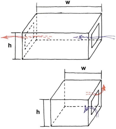
The most suitable shape and layout for naturally ventilated buildings is very similar to that discussed for daylighting. In a building with good crossflow, a natural ventilation strategy will only be effective up to a maximum distance of around 15 metres over an open-plan layout. Hence a long, narrow floor plate is the preferred building form.
One-sided ventilation is only effective for less than half this distance, but is still a good strategy for venting cellular offices or enclosed spaces along one side of the building.
Figure 14: Ventilation guidelines for room dimensions

Care should be taken, however, to ensure the form of the building also suits the site and surroundings.
Windows and vents
The easiest method of bringing outdoor air into a room is to open a window. This is most suitable for cellular offices or classrooms where the occupants are more likely to take ‘ownership’ of the space and use the window effectively. Adjustable louvres and small, thin ‘trickle’ vents can be used to provide ventilation when a window cannot, for example during high winds or rain. Ideally, users should have the choice of more than one option.
Openings can be automated and controlled by the BMS, though this adds to the project cost. The control system should also include rain and wind sensors to ensure vents do not open during bad weather.
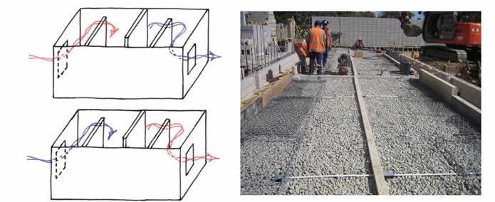
Atriums
One of the many functions of an atrium is to provide natural ventilation to areas that are difficult to ventilate from the perimeter. The atrium’s height allows a temperature gradient to develop, which then creates air movement through the stack effect. Warm air is released at a high level and outdoor air is brought into the building at the perimeter.
Figure 15: A typical natural ventilation strategy with an internal atrium

Lightwells can also be used for natural ventilation if space requirements do not allow the inclusion of a full-sized atrium.
Naturally ventilated atriums may not meet the simple Building Code requirements for smoke extraction. If that is the case, a fire engineer will have to prove compliance through an alternative solution.
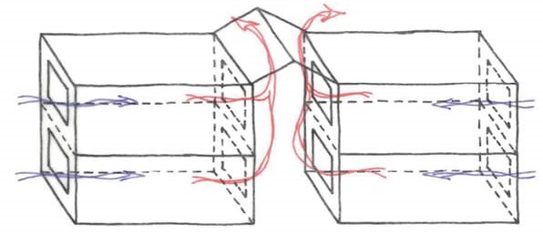
Double-skin facades
Over the height of a building, a significant temperature gradient can develop, particularly within the glazed layers of a double-skin facade. The superheated air then rises and is released by vents at the top of the facade. Air is vented from the interior spaces into the facade through automated vents in the inner skin.
Figure 16: Typical natural ventilation strategies within a double-skin facade

Ventilation and solar chimneys
Similar to a lightwell, though often smaller and enclosed, a ventilation chimney extends above the roofline of a building to vent hot air through the stack effect and/or wind pressure. Internal areas are vented into the chimney. Solar ventilation chimneys include highly glazed areas to increase the temperature gradient within the chimney. Glazed stairwells can also be used for this purpose, as they are effectively a riser that extends throughout the height of the building.
Wind vanes and their control
It is important that design teams consider not only the wind resource at the site, but also the effect the building itself will have on that wind resource, and attempt to use it. The building form can direct air into the space and draw air into the intakes. Using the shape of the building to guide the wind reduces any cost premiums. Additional wind control devices, such as sails or wind vanes that extend into the airflow, can be interesting architectural features, but add to construction costs.
The same considerations apply when using wind generation. Turbines tend to be placed on the roof of the building; however, windflow over the top of a building is often turbulent and low quality. Windflow is often more reliable around the corners of buildings, or in the channelled flow between two neighbouring buildings.
Evaporative cooling
If the site includes a reasonable body of water, or if water features can be incorporated into the design, evaporative cooling may be an option for increasing the cooling potential of a natural ventilation design strategy. The evaporation that occurs at the surface of water extracts heat from the air and, as the temperature of the air falls, its relative humidity rises. Although difficult to apply inside, it can be used if water can be placed at or near the outdoor air source. To optimise evaporative cooling and movement of air and water, extensive water-to-air surface contact is needed. This can be achieved with landscape features, such as ponds, as in the Christchurch Library with its ‘moat’ surrounding the low-level opening windows.
Night purge
This was discussed in greater detail in the section on thermal mass and insulation. If night purging of residual heat is part of the conditioning strategy, the natural ventilation system needs to be designed so that it still performs during cooler night-time temperatures. Vents need to be secure and closed in bad weather.
3.5.2: Natural ventilation checklist
- Use information from the site investigation to determine a suitable ventilation strategy.
- Design building layout and orientation to exploit high- or low-gain areas for ventilation purposes.
- Design the ventilation strategy and align with heating, cooling and shading strategies.
- Refine the strategy throughout the design process, possibly using CFD on larger buildings or for major design features (eg, atriums).
- Mitigate any potential issues with noise intrusion, smoke extraction and so on.
- Ensure the system is commissioned to best practice standards.
Using computer modelling to predict the daylighting and thermal or energy performance of buildings is becoming increasingly prevalent, particularly with the introduction of Green Star rating tools, where thermal and energy modelling is a conditional requirement.
Modelling can also be used as a compliance method for the energy efficiency and natural light (for domestic situations) clauses of the New Zealand Building Code. While these applications provide a snapshot of a building’s potential, building simulation is best used throughout the design process as a tool to compare and optimise different design strategies (for example, window size, glazing type, arrangement of thermal mass and insulation).
Good passive solar design depends on the complex interaction of several aspects of a building’s design. Computer modelling can help designers deal effectively with the complexity of these passive solar design issues, identify and resolve problems of comfort, building performance and energy use, and analyse and fine-tune the design. This accelerates the design process by quickly identifying problems and opportunities, and narrows the range of practical solutions, saving time and money for both the design team and client.
Once a set of workable options is chosen, computer simulation can ‘fine tune’ the energy-saving strategies and indicate what the comfort levels and energy use of the building are likely to be. The whole building will perform more effectively because the designer will have more information about the interaction between the solar features and the other elements of the building’s design.
In a conventional building, computer modelling is normally carried out by the service engineers as part of the mechanical services (HVAC) design, though some projects use specialist environmentally sustainable design (ESD) consultants. In a passive building, where the intent may be to not provide HVAC, modelling would be used to ensure the passive design strategies will perform well enough to meet the building’s desired internal conditions.
In a conventional building, designers tend to use simple rules of thumb and experience through the concept and preliminary design stages before incorporating modelling results throughout the developed design stage. On the other hand, a passive building requires feedback from the modelling process to be incorporated as early as possible. It is more likely that passive solar features will be central to the design and form of the building. The modelling tool can also provide useful information on the climate and shading conditions at the site that can then be fed into the preliminary design.
In general, a building simulation package will contain the following information:
- building description – size, shape, orientation, window type, size and orientation, construction material types and their physical properties (eg, thermal conductance, density, and reflectance)
- design data – insulation levels, internal gains from lights, small power and occupants, infiltration and ventilation rates, equipment efficiencies and desired temperature setpoints
- site data – sky information, weather data files (standard files on hourly temperatures, solar radiation and wind information are available from the Department of Energy in the United States or within the software itself).
The computer model produces information about the:
- extent of shading and solar access to the site
- climatic conditions using the averaged annual weather data or extreme design conditions
- hourly internal temperatures and comfort conditions
- extent of daylight penetration and likely illuminance levels
- annual, seasonal, monthly, daily or hourly heating and cooling loads
- peak heating and cooling loads
- auxiliary energy consumption.
Care does need to be taken with computer simulation, especially when entering the information into the software, as initial assumptions will need to be made about the building and its design. If those assumptions are inaccurate, this will have a corresponding effect on the modelling results (a phenomenon normally known as ‘garbage in, garbage out’). During a comparative study of two or more scenarios, the effect of any inaccuracies is negated, which is why this method is preferred over a one-off, standalone simulation. When using computer simulation, design teams and modellers should also be conscious of the difference between accuracy (having valid assumptions) and precision (having exact assumptions).
Most experienced engineers will have a good intuitive feel for how a building should perform, and modelling leads to a sense of ‘advanced intuition’. Intuition can be used to check modelling results, while modelling is used to refine intuition and allow quick comparison of building variations. As a result, the design team should have a good working knowledge of the basic concepts of passive solar design. Building simulation is not a substitute for knowledge, but a means of quantifying, refining and calculating the impact of design decisions.
A computer model’s predictions of building performance can be used to establish targets for the building’s energy and water use, and even internal conditions. Care should be taken due to differences in the modelling assumptions from the actual building’s use, or weather conditions experienced by the building compared with the weather data used by the software. Such targets then become important performance indicators through the operation of the building, or within a performance-based lease agreement. Information on performance-based leases is included in the further reading section.
The value of computer simulation for achieving a high-quality building, with potential for significant energy savings, is becoming well established. Properly incorporating simulations into the design process can save the design team time and money, improve client satisfaction, suggest energy opportunities that might otherwise be overlooked, and solve problems that could be difficult and include a cost to change while they are still on the drawing board instead of built into a building.
3.6.1: Building simulation checklist
- Assess the extent of shading and solar access to the site.
- Use computer simulation software and tools to help the site investigation process.
- Model the building fabric at the preliminary stage to determine a baseline level of ‘natural performance’ (eg, the level of comfort and internal illuminance without any artificial systems in the building).
- Compare possible strategies and quantify their effect on comfort and energy use.
- Refine the design during the developed design phase, incorporating any additional lighting or HVAC systems.
- Finalise the model with the design to establish performance targets for future building operation. This model can also be used for Building Code compliance or Green Star submissions, if required.
See more on...
3: Guidance on Passive Solar Design
December 2008
© Ministry for the Environment